
Blog
Antennino: Tutorial & Setup Guide
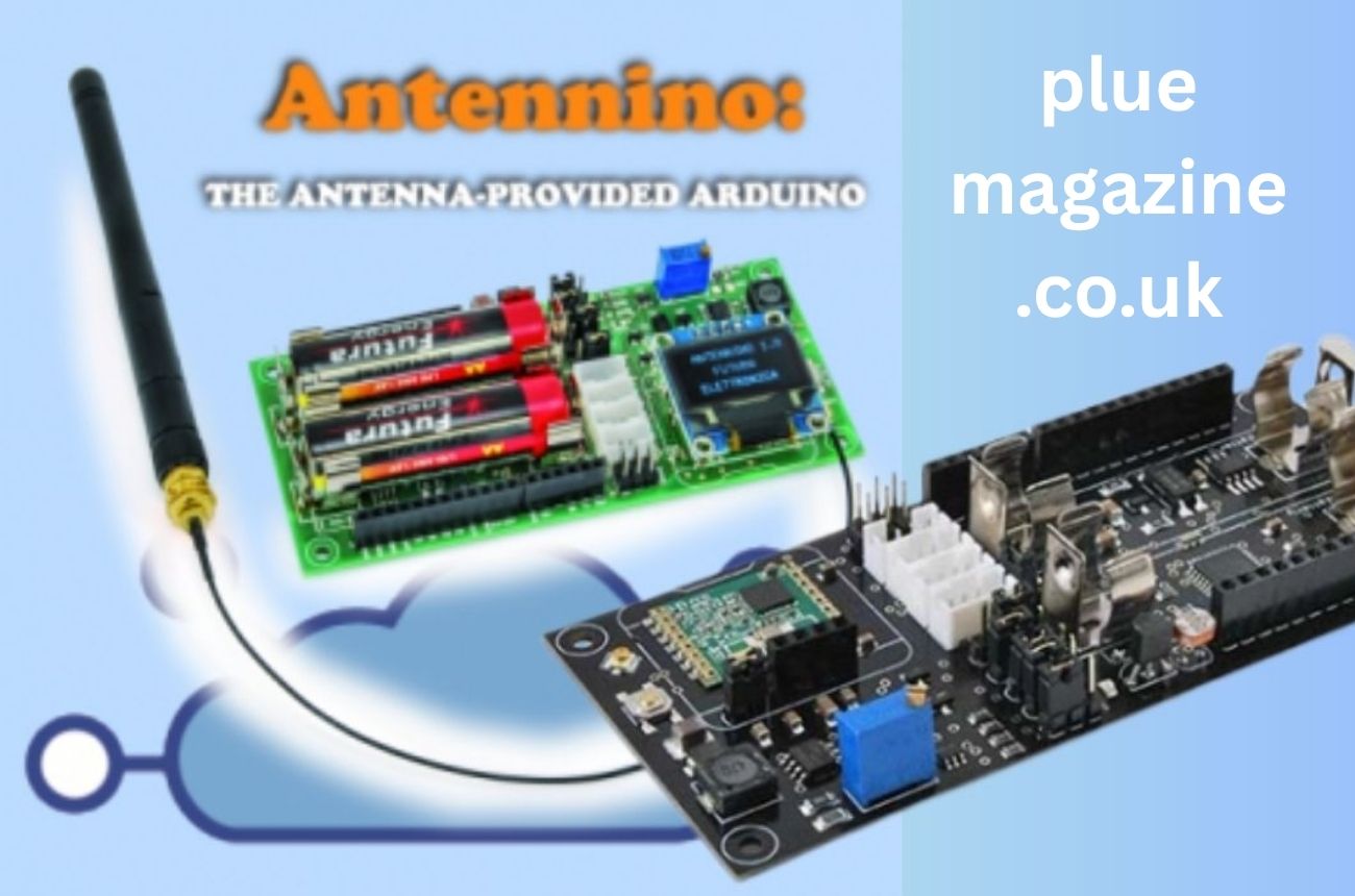
In the rapidly evolving field of Internet of Things (IoT) and wireless communication, Antennino has emerged as a compact yet powerful solution for enthusiasts and developers. At its core, Antennino is an Arduino-compatible, low-power wireless node designed for creating smart and interconnected devices. Its architecture makes it ideal for long-range communication with minimal energy consumption. Unlike many standard microcontrollers, Antennino integrates both computing and communication modules, making it a self-contained tool for IoT applications. This tutorial explores every aspect of Antennino — from setup and programming to practical applications — to help you understand how to make the most of this innovative device.
What Makes Antennino Unique
The uniqueness of Antennino lies in its hybrid design that merges microcontroller logic with RF (radio frequency) communication. Built around the Atmega328p microcontroller — the same chip used in Arduino Nano — Antennino comes preconfigured with a built-in RFM69 radio module for wireless data transmission. This combination eliminates the need for separate RF modules, reducing wiring complexity and physical size. Furthermore, it offers a sleep mode for ultra-low power consumption, enabling years of operation on a single coin cell battery. This innovative design philosophy marks Antennino as a major step forward for hobbyists, educators, and engineers.
Core Components of Antennino
Before diving into the setup, it’s crucial to understand the main components that make up the Antennino board:
-
Microcontroller (Atmega328p): Handles core processing and logic.
-
RFM69 Radio Module: Manages RF transmission and reception between devices.
-
On-board Antenna: Facilitates strong wireless communication.
-
Power Management Circuit: Optimizes battery efficiency and sleep functions.
-
Programming Connector: Allows firmware uploading through USB-to-serial adapters.
These integrated components make Antennino an all-in-one solution for low-power, wireless projects without needing extra shields or modules.
Setting Up Your Antennino for the First Time
Setting up Antennino is straightforward, especially for users familiar with the Arduino IDE. First, download and install the latest Arduino software from the official website. Next, connect the Antennino board using an FTDI USB-to-Serial adapter, since it doesn’t come with a built-in USB interface. Choose “Arduino Pro or Pro Mini” as the board type, set the processor to “ATmega328 (3.3V, 8MHz)”, and select the correct COM port. Once done, upload a simple “blink” sketch to verify connectivity. This initial setup ensures your Antennino is ready for wireless configuration and custom programming.
Installing Required Libraries
To leverage the full potential of Antennino’s radio capabilities, certain libraries must be added to the Arduino environment. The LowPowerLab’s RFM69 library is essential for radio communication. You can install it via the Arduino Library Manager or manually by downloading it from GitHub. Additionally, for managing sensor data, you can include libraries such as Adafruit Sensor or BME280 for environmental monitoring. These libraries simplify the communication between the Antennino board and external sensors or modules.
Configuring the Antennino Radio Network
Each Antennino operates as a node within a wireless network. To establish communication, you must assign a unique node ID to each board. For instance, node ID 1 could act as the base station (connected to your computer), while other nodes (ID 2, 3, etc.) send sensor data to it. Within your code, define network parameters such as frequency band (433 MHz or 868 MHz), network ID, and encryption key for secure communication. This simple configuration allows Antennino nodes to communicate efficiently over long distances — up to several hundred meters depending on the environment.
Power Efficiency and Sleep Mode
One of Antennino’s biggest strengths is its power efficiency. When running on battery power, Antennino can enter a deep sleep mode, consuming as little as a few microamps. Developers can program the device to wake up periodically — for example, every 10 minutes — to send sensor data and then return to sleep. This feature is vital for remote monitoring systems where constant power sources aren’t available. By combining smart sleep algorithms with low-voltage hardware, Antennino can operate for years on a single CR2032 battery.
Adding Sensors and Peripherals
Antennino is fully compatible with a wide range of sensors and peripheral devices. You can connect temperature, humidity, or motion sensors through the I²C or SPI interfaces. For instance, integrating a DHT11 temperature sensor allows you to transmit environmental data wirelessly to a central hub. Similarly, you can use an LDR (light-dependent resistor) for light intensity monitoring. The open nature of Antennino means developers can experiment freely with hardware combinations to achieve custom IoT solutions.
Creating a Base Station

A base station serves as the receiver hub for all wireless nodes. To build one, connect an Antennino to your PC using an FTDI adapter and configure it as a “gateway” node. The base station listens for data from other nodes and can visualize it using serial monitor software or dashboards such as Node-RED. This setup is ideal for creating small-scale home automation networks or research projects involving multiple sensors across different locations.
Data Transmission and Encryption
Security is often overlooked in small IoT systems, but Antennino provides built-in AES encryption for safe data transfer. When programming your network, define an encryption key (16 characters long) that will be shared across all nodes. This prevents unauthorized devices from intercepting or altering the transmitted information. Furthermore, developers can include checksum validation to ensure data integrity. These advanced but user-friendly features make Antennino suitable for professional-grade wireless systems.
Troubleshooting Common Issues
Like any programmable device, Antennino may face issues such as uploading errors, range limitations, or communication loss. If your code fails to upload, check your FTDI driver installation or reset the board manually before uploading. For range problems, ensure the antenna is properly soldered and positioned vertically. Additionally, reduce environmental interference by adjusting the transmission power level or changing the frequency band. Understanding these troubleshooting basics will save time during testing and deployment.
Real-World Applications
Antennino’s versatility extends across numerous fields. In smart agriculture, it can monitor soil moisture and transmit data to a base station for irrigation control. In home automation, Antennino can control lighting, doors, or alarms wirelessly. Industrial users employ it for predictive maintenance — tracking machinery vibrations or environmental conditions to prevent equipment failure. Its modularity and low power draw make it a preferred choice for researchers and tinkerers aiming to create autonomous IoT ecosystems.
Community Support and Future Prospects
The Antennino community continues to grow, offering tutorials, open-source code, and hardware designs. Many developers contribute to GitHub repositories to enhance firmware stability and add new features. Looking ahead, Antennino could see integration with LoRaWAN and Wi-Fi bridges, extending its communication range even further. There’s also ongoing development to include energy-harvesting support, which could make Antennino a self-sustaining IoT device powered by solar or kinetic energy.
Conclusion
Antennino represents a fusion of simplicity, efficiency, and innovation. It brings the power of Arduino programming together with reliable RF communication, empowering developers to create connected devices that are both practical and energy-efficient. Its low-cost design, combined with strong community support, positions it as one of the most accessible tools for IoT experimentation. Whether you’re a hobbyist or a professional, understanding Antennino’s setup, configuration, and applications opens the door to endless possibilities in wireless communication technology.
FAQs
1. What is the primary purpose of Antennino?
Antennino is primarily designed for low-power wireless communication in IoT projects. It allows devices to send and receive data over long distances without continuous power, making it suitable for remote sensing, home automation, and research applications.
2. How does Antennino differ from a regular Arduino board?
While standard Arduino boards need external RF modules, Antennino comes with an integrated RFM69 radio chip and built-in power management. This integration simplifies hardware setup and improves energy efficiency, making Antennino superior for long-term wireless projects.
3. Can I power Antennino with regular batteries?
Yes. Antennino can be powered by coin-cell batteries, AA batteries, or small LiPo cells. Its ultra-low power consumption means it can run for months or even years on a single battery, depending on the duty cycle and application.
4. What range can Antennino achieve for communication?
Under ideal conditions, Antennino can achieve a range of up to 500 meters in open space. Factors like obstacles, antenna type, and interference can affect this range, but it remains highly effective for medium- to long-range IoT projects.
5. Is Antennino suitable for beginners?
Absolutely. Antennino maintains Arduino compatibility, meaning users can program it through the Arduino IDE using familiar syntax and libraries. Its modular and plug-and-play nature makes it easy for beginners to explore wireless IoT development confidently.

Private ADHD Assessment UK: What Parents Should Know

Local Portland Plumbers: Understanding Community-Based Service Excellence

8 Reasons People in Surrey Are Turning to Dermal Fillers for Subtle Refreshment

How Made in China Wholesale Shapes the Future of International Business

Stirring Up Success: How Online Culinary Schools Are Changing the Face of Gourmet Training

How UK Bodybuilders Use Mix Compounds to Simplify Cycles

Strategic Instagram Followers Growth Without Damaging Brand Credibility

Where to Buy Designer Wedding Dresses That Balance Comfort and Elegance

The Benefits of Using Altify Teamview for Sales Teams

Best AI Text to Video Generators of 2025: Create Professional Videos from Simple Text

Nathaniel Mandrell Dudney: Insights into Barbara Mandrell’s Family Life

Who Is Elizabeth Buckley Harrold O’Donnell? A Closer Look at Lawrence O’Donnell’s Family

Who Is Vera Davich? A Deep Dive into Her Life and Relationship with Scott Patterson

Melanie Sergiev & Drew Lynch: How Their Partnership Shapes Their Professional and Personal Worlds

Meet Vladislava Galagan: A Profile of Her Life and Impact

Talia Elizabeth Jones: Exploring Her Connection to Davy Jones

Who is Jasmine Gong? Exploring Her Life and Connection to Brad Williams

Who is Noelle Inguagiato? Exploring the Life of Jesse Watters’ Wife

Who is Heidi Van Pelt? Exploring Taran Noah Smith’s Ex-Wife and Their Family Journey

Who Is Pearl Minnie Anderson? Exploring Maya Rudolph’s Life as a Mother
Private ADHD Assessment UK: What Parents Should Know
Local Portland Plumbers: Understanding Community-Based Service Excellence
8 Reasons People in Surrey Are Turning to Dermal Fillers for Subtle Refreshment
How Made in China Wholesale Shapes the Future of International Business
Stirring Up Success: How Online Culinary Schools Are Changing the Face of Gourmet Training
How UK Bodybuilders Use Mix Compounds to Simplify Cycles
Strategic Instagram Followers Growth Without Damaging Brand Credibility
Where to Buy Designer Wedding Dresses That Balance Comfort and Elegance
The Benefits of Using Altify Teamview for Sales Teams
Best AI Text to Video Generators of 2025: Create Professional Videos from Simple Text
-
 Celebrity12 months ago
Nathaniel Mandrell Dudney: Insights into Barbara Mandrell’s Family Life
-
 Celebrity11 months ago
Who Is Elizabeth Buckley Harrold O’Donnell? A Closer Look at Lawrence O’Donnell’s Family
-
 Celebrity11 months ago
Who Is Vera Davich? A Deep Dive into Her Life and Relationship with Scott Patterson
-
 Celebrity11 months ago
Melanie Sergiev & Drew Lynch: How Their Partnership Shapes Their Professional and Personal Worlds